
Designing a data center means managing consequences. The final product is not the building, but the continuous, secure delivery of computing capacity, connectivity, and storage. This guide covers the full chain of decisions — from the business case and risk analysis to thermal and electrical engineering, telecommunications, protection, construction, commissioning, and operation.
The sequence is always the same: the business case defines criticality; criticality defines requirements; requirements define the design; the design is proven through testing; and operation preserves the performance achieved. Skipping a step transfers uncertainty to the construction phase, where changes cost more and jeopardize schedule.
About this material: the architectures presented are reference examples and do not replace an executive design, technical report, professional liability, or consultation with the current editions of applicable standards. Redundancy is not automatically synonymous with availability: the outcome depends on physical independence, selectivity, automation, procedures, integrated testing, and operational competence.
Executive summary
Each part of the guide answers a specific decision. Use the table as a reading map: managers should start with the first four rows; engineering should move through the technical disciplines; operations should focus on commissioning, documentation, and indicators; procurement should use the matrices and checklists to structure the RFP, technical equalization, and acceptance.
| Part | Content | Main decision |
|---|---|---|
| Fundamentals | Objective, typologies, and life cycle | Build, contract colocation, edge, or hybrid? |
| Requirements and risks | BIA, criticality, threat, and tolerance | Which interruption is acceptable and at what cost? |
| Availability | Classes, topologies, maintenance, and failures | Which architecture meets the service? |
| Planning | Capacity, area, density, and expansion | How much, when, and where to build? |
| Thermal | Airflow, DX, chilled water, and liquid cooling | How to remove heat with stability and efficiency? |
| Electrical | Grid, GMG, UPS, batteries, ATS, PDU, and protection | How to deliver safe power up to the IT load? |
| Telecom | Routes, MMR, cabling, and topologies | How to eliminate hidden dependencies? |
| Protection and control | Fire, access, CCTV, BMS, and DCIM | How to detect, contain, and respond? |
| Construction and delivery | Materials, stages, QA/QC, and commissioning | How to prove the design works? |
| Operation and future | SLA, maintenance, PUE, AI, and high density | How to sustain reliability over time? |
What is a data center
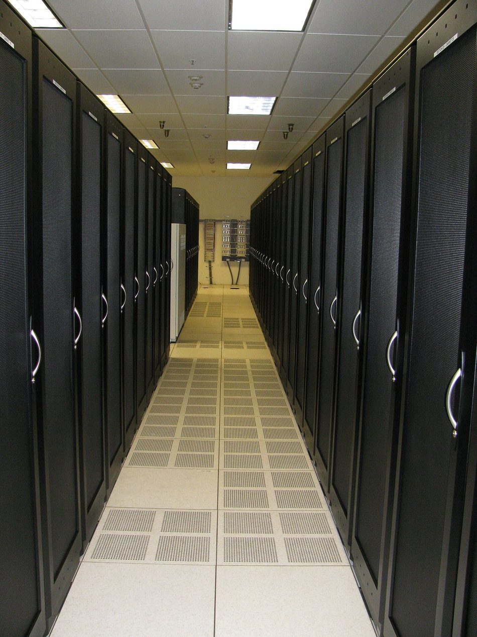
A data center is the coordinated set of spaces, utilities, controls, and processes that sustains technology and telecommunications equipment. Power, cooling, and networks are service chains; each link needs capacity, protection, monitoring, and a maintenance path.
| Layer | Examples | Typical failure |
|---|---|---|
| Business | Services, customers, legislation, revenue | Poorly defined criticality |
| IT and telecom | Compute, storage, network, platforms | Demand exceeding capacity |
| Facilities | Power, cooling, fire, security | Single point of failure |
| Operations | People, processes, parts, and suppliers | Human error or delayed response |
Principle: critical infrastructure must be designed around the service that needs to survive, not just the equipment that will be installed.
The full life cycle runs from strategy and requirements to the preliminary study, conceptual design, basic and executive design, contracting, construction, testing, operation, optimization, and finally expansion or decommissioning.
Types and deployment models
| Model | Advantage | Attention point |
|---|---|---|
| Enterprise | Control and integration with the business | CAPEX, scale, and specialized team |
| Colocation | Speed, connectivity, and shared infrastructure | Contract, demarcation of responsibilities, and cross-connects |
| Hyperscale | Scale, standardization, and automation | High demand for power, water, and land |
| Edge | Low latency and proximity to the user | Distributed sites, maintenance, and physical security |
| Modular/prefabricated | Schedule and repeatability | Civil interfaces, logistics, and expansion |
| Hybrid | Flexibility across sites and clouds | End-to-end operational architecture and observability |
The build-versus-contract comparison must incorporate total cost, schedule, regulatory risk, available power, connectivity, expansion capacity, useful life, cost of capital, staffing, obsolescence, and contractual flexibility. A seemingly cheap in-house room may require disproportionate electrical and thermal retrofitting; colocation can reduce lead time, but requires an SLA, audit, and exit plan.
- Map loads that cannot leave the site and those that can be distributed.
- Model at least three growth scenarios and one stress scenario.
- Include the cost of downtime, not just CAPEX and monthly fees.
- Define who is responsible for each segment: utility, data center, rack, equipment, and application.
Requirements in balance
A viable project balances three groups: business defines what needs to continue; engineering translates that into capacity, topology, and performance; finance sets the investment and operating envelope. This balance must be documented in a Basis of Design (BoD), with assumptions, exclusions, and acceptance criteria.
| Group | Essential questions |
|---|---|
| Business | Which services? Who is affected? What window? What contractual or legal obligation? |
| Technical | Initial and future load? Density? Autonomy? Routes? Maintainability? |
| Financial | CAPEX, OPEX, contingency, cost of capital, energy, maintenance, and renewal? |
| Operational | Staff, 24x7 coverage, spare parts, suppliers, procedures, and training? |
The Owner's Project Requirements (OPR) document consolidates this decision and must contain:
- Project objectives and scope.
- Load profile and growth horizon.
- Availability, security, and efficiency criteria.
- Environmental conditions and operating limits.
- Metering, alarms, integration, and data retention.
- Testing, documentation, training, and warranty.
BIA and business risk
The Business Impact Analysis identifies critical processes, dependencies, maximum tolerable downtime, and progressive impacts. The RTO guides the recovery time; the RPO guides the maximum acceptable data loss. They do not replace the facilities analysis, but they prevent infrastructure from being sized based on perception.
| Impact | Example evidence | Treatment |
|---|---|---|
| Financial | Lost revenue, penalties, rework | Quantify per hour and per event |
| Operational | Backlog buildup, productivity loss | Model degradation and recovery |
| Legal/regulatory | Deadlines, data retention, security | Validate with legal and compliance |
| Reputation | Churn, press, trust | Use scenarios and indicators |
| Life/safety | Medical services, emergency, control | Minimum tolerance and formal response |
Probability and consequence must be supported by history, asset condition, exposure, and existing controls. Residual risk is what remains after mitigation — accepting it is a decision by the risk owner, not an omission in the design.
Example: if a power failure can interrupt R$ 300 thousand per hour and the likely recovery time is 4 hours, the direct reference impact is R$ 1.2 million — before penalties, image, and operational recovery.
Internal and external risks
| Domain | Threats | Verification |
|---|---|---|
| Location | Flood, landslide, external fire, aircraft crash | Maps, history, exposure radius, and inspection |
| Utilities | Weak power grid, fuel, water, telecom | Feasibility letters and physical routes |
| Building | Structural load, water above critical room, vibration | Survey and testing |
| Fire | Combustible load, compartmentalization, detection | Legal design and cause/spread analysis |
| People | Improper access, error, lack of training | Segregation, procedure, and training |
| Supply chain | Lead time, exclusive part, single supplier | Critical list and strategic stock |
| Cyber-physical | Exposed BMS/DCIM, weak credentials | Segmentation, hardening, backup, and logging |
- Risk register with owner, deadline, and evidence.
- FMEA for failure modes, effects, and controls.
- HAZOP or What-if for process deviations.
- Fault Tree for combinations leading to the top event.
- Bow-tie to visualize prevention, event, and mitigation.
Availability without oversimplification
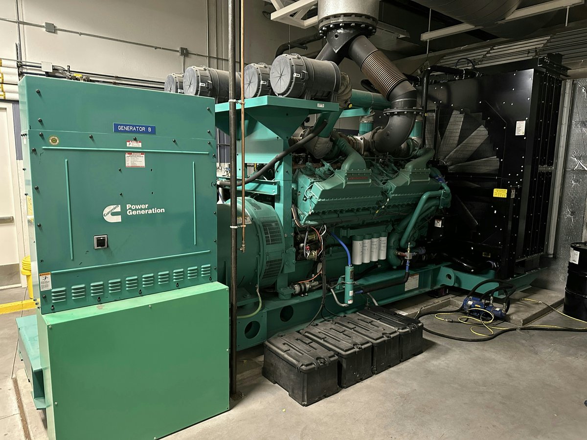
Availability is the proportion of time the service is able to perform its function. For a repairable component, a common approximation is A = MTBF / (MTBF + MTTR). In a data center, however, common dependencies, human failures, maintenance, controls, and operational response make systemic behavior far more complex than the formula suggests.
| Concept | Practical meaning |
|---|---|
| N | Capacity needed to support the design load |
| N+1 | One additional module beyond what is needed |
| 2N | Two complete and independent systems |
| 2(N+1) | Two complete systems, each with an additional reserve |
| Concurrent maintenance | Remove a component or path in a planned manner without stopping the load |
| Fault tolerance | A failure does not cause immediate interruption of the critical load |
- Two devices fed by the same panel do not form independent paths.
- Logical redundancy without physical separation can fail from a single event.
- A single-cord load requires an STS or a specific architecture; dual-cord loads must have consistent A/B distribution.
- Rated battery autonomy varies with load, temperature, age, and discharge regime.
Classes and reference standards
The ISO/IEC 22237 series classifies infrastructure by availability, security, and efficiency across the life cycle. The Uptime Institute uses Tier criteria oriented to topology and operational performance. Levels and classes from different reference standards should not be treated as automatically equivalent: the contractual requirement must indicate the standard, edition, scope, and method of proof.
| Intent | Typical architecture | Validation question |
|---|---|---|
| Basic capacity | Single path and sized components | Does a planned maintenance require shutdown? |
| Redundant components | N+1 in parts of the chain | Is there still a single path? |
| Maintainability | Multiple paths and isolation | Can each component be maintained with an active load? |
| Fault tolerance | Segregation and automatic response | Does an isolated failure interrupt the load? |
Caution: do not advertise certification, class, or Tier based solely on a diagram. Certification depends on the program, scope, documentation, construction, and/or operation as evaluated by the relevant authority.
Dual-path electrical architecture
The A/B principle creates two power paths up to the critical load. To be effective, it must consider source, generation, transformation, switching, UPS, distribution, cables, PDU, and equipment connection. Shared components must be identified and justified — not discovered during a failure.
- N capacity during maintenance and under the defined failure condition.
- Selectivity and protection coordination across all operating modes.
- Testable interlocks and transfer logic.
- Physical separation against fire, water, and intervention.
- Metering points from the utility to the rack.
- Safe bypass plan and return to normal condition.
From IT inventory to design power
Sizing begins with an inventory of equipment, measured or declared power, coincidence factor, usage profile, growth, and reserves. Nameplate power is not average consumption — but the design also cannot ignore peaks, transients, simultaneous boot, battery recharge, and degradation.
| Stage | Reference calculation |
|---|---|
| Initial IT load | Sum per equipment × utilization and coincidence factor |
| Growth | Annualized scenarios or by installation waves |
| Rack capacity | Electrical, thermal, physical, and floor limits — the lowest applies |
| IT thermal load | Approximately equal to the electrical power dissipated in steady state |
| Infrastructure | IT + cooling + losses + lighting + auxiliaries |
| Reserve | Explicit margin, without duplicating conservative factors |
Example: 100 racks × 8 kW = 800 kW of IT load. With a design PUE of 1.45, the average total reference power would be 1.16 MW. The electrical system must still account for failure modes, maintenance, startups, and rated capacity.
Density and rack strategy
Density can be expressed in kW/rack, kW/m² of room, or per computing unit. The average hides hotspots: an 8 kW/rack room can contain 30 kW islands. The design must separate zones, define per-rack limits, and reserve evolution paths for liquid cooling.
| Indicative range | Typical application | Thermal strategy |
|---|---|---|
| Up to 5 kW/rack | Conventional IT or low occupancy | Organized aisles and bypass control |
| 5 to 15 kW/rack | Virtualization and storage | Containment and units with modulation |
| 15 to 30 kW/rack | Dense compute and moderate accelerators | In-row/rear-door or highly controlled air |
| Above 30 kW/rack | HPC and high-density AI | Evaluate direct-to-chip, CDU, and technology water |
The ranges are indicative. The decision depends on the required flow rate, equipment ΔT, available pressure, layout, thermal tolerance, and manufacturer specification.
- Width and depth compatible with equipment and cabling.
- Aisles for circulation, maintenance, and component removal.
- Cable management without blocking exhaust.
- Blanking panels and sealing of openings.
- Grounding, bonding, and labeling.
Site selection
| Criterion | Due diligence questions |
|---|---|
| Power | Firm capacity? Voltage? External redundancy? Connection lead time? Quality? |
| Telecom | How many carriers? Truly diverse routes? Opposite entrances? |
| Environmental | Climate, water, noise, emissions, permits, flooding, and neighborhood |
| Civil | Soil, load, vibration, height, access, and equipment logistics |
| Operations | Labor, fuel, parts, security, and response time |
| Expansion | Area, utilities, phases, interferences, and continuity during construction |
In an existing building (brownfield), perform an as-built survey, scanning when applicable, load testing, panel and cable inspection, structural analysis, and verification of water above or beside critical areas. The invisible constraint often defines the design: shaft, exhaust route, ceiling height, floor load, fire protection, or rigging access.
Thermal fundamentals
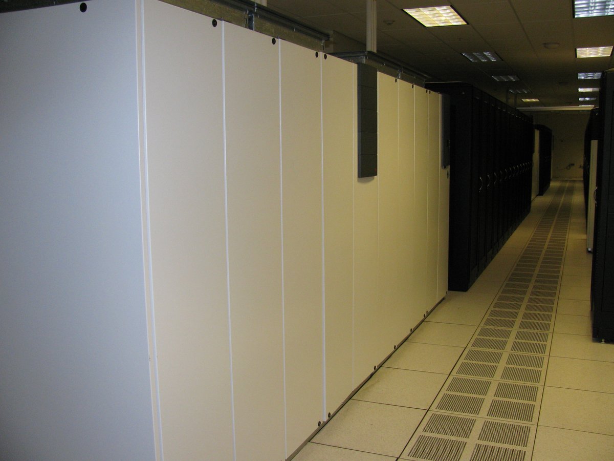
Nearly all electrical energy consumed by IT converts into heat. The thermal system's task is to capture that heat at the source, transport it, and reject it to the environment, keeping the equipment's inlet within the defined range. Average room temperature does not reveal recirculation, bypass, or hotspots.
| Phenomenon | Effect | Control |
|---|---|---|
| Recirculation | Hot air returns to the rack inlet | Containment, sealing, and proper pressure |
| Bypass | Cold air does not pass through the IT | Flow adjustment, blanking panels, and layout |
| Mixing | Reduces ΔT and efficiency | Physical segregation of flows |
| Low flow | Inlet temperature rises | Capacity, fans, and clear paths |
| Excessive flow | Wasted energy and undue pressure | Demand-based modulation |
Environmental parameters
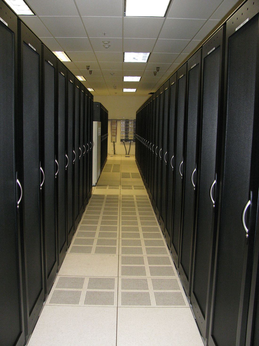
Environmental classes must be defined according to the equipment installed. As a widely used reference, ASHRAE TC 9.9 indicates a recommended range of 18 °C to 27 °C for classes A1 through A4; allowable limits vary by class and should not be confused with a permanent operating target. Humidity must be managed by dew point, condensation risk, electrostatics, and corrosion.
| Parameter | Why measure it | Best practice |
|---|---|---|
| Inlet temperature | The air actually received by the IT | Sensors per rack and height, not just on the wall |
| Humidity and dew point | Condensation, ESD, and corrosion | Trend and consistent alarms |
| Differential pressure | Confirms flow direction | Measure between relevant zones |
| Particulates and corrosion | Electronic reliability | Filtration, sealing, and coupons when necessary |
| Water leakage | Early detection | Sensors per zone and periodic testing |
Tape equipment, batteries, and power components may have different limits. The manufacturer's specification and warranty conditions prevail.
Cooling technologies
| Solution | When it makes sense | Points of attention |
|---|---|---|
| Direct expansion (DX) | Small, modular, or distributed sites | Refrigerant, distance, redundancy, and partial efficiency |
| Chilled water | Medium and large scale, centralization | Pumps, chiller, tower/dry cooler, water, and controls |
| In-row | Hotspots and proximity to the load | Hydraulic or refrigerant distribution in the room |
| Rear-door | Retrofit and high density | Weight, hoses, condensation, and maintenance |
| Direct-to-chip | High-density CPU and GPU | CDU, water quality, pressure, detection, and interfaces |
| Immersion | Specific loads and very high density | Fluid, maintenance, compatibility, and operation |
Compare total cost, local climate, water availability, density, modularity, part-load efficiency, concurrent maintenance, area, noise, refrigerants, leak risk, and team capability. The best COP of an isolated unit does not guarantee the best system performance.
Thermal sizing and controls
Capacity must be verified for outdoor design conditions, sensible load, losses, redundancy, and degraded modes. Adding up rated capacities without confirming curves, water and air temperature, altitude, and flow rates creates false confidence.
| Verification | Acceptance question |
|---|---|
| Thermal balance | Have all heat sources and scenarios been included? |
| Psychrometrics | Is there control against condensation and excessive humidification? |
| Hydraulics | Are pressure drop, valve authority, and balancing proven? |
| Controls | Have the sequence of operation and setpoints been reviewed? |
| Failure and maintenance | Does the temperature remain acceptable under the defined event? |
| Dynamic testing | Have load steps and transfers been simulated? |
Metric: installed capacity is not enough. Track available, used, and committed capacity per zone, always considering the limiting component.
Critical electrical chain
The typical chain includes the utility, medium voltage, transformation, panels, generation, transfer, UPS, distribution, and rack. Each stage must be analyzed under normal condition, maintenance, failure, emergency, and return to normal.
| Component | Function | Critical risk |
|---|---|---|
| Entry and MV | Receive, switch, and protect | Arc flash, coordination, and external outage |
| Transformer | Adjust voltage and isolate | Capacity, temperature, harmonics, and fire |
| GMG | Supply prolonged outage | Startup, fuel, emissions, and heat rejection |
| ATS/STS | Transfer sources and paths | Logic, synchronism, and switching failure |
| UPS | Condition and sustain transition | Bypass, battery, overload, and common-mode failure |
| PDU/RPP/busway | Distribute and meter | Selectivity, expansion, and connection error |
Generator sets and fuel
The generator must meet steady-state load and transient steps, including motors, UPS, recharge, cooling, and auxiliaries. The analysis must consider startup sequence, voltage and frequency dip, short-circuit capacity, altitude, temperature, fuel, and emissions.
| Topic | Criterion |
|---|---|
| Autonomy | Defined by risk, refueling contract, and crisis scenario |
| Tanks | Usable capacity, containment, detection, transfer, and fuel quality |
| Startup | Redundant batteries and chargers, pre-heating, and testing |
| Paralleling | Control, synchronism, load sharing, and protection |
| Maintenance | Access, parts, load bank, and planned downtime |
| Exhaust and noise | Back pressure, temperature, dispersion, acoustics, and permits |
Meaningful test: a weekly no-load startup does not prove the chain. The program must include tests under load, source failure, transfer, stability, operational autonomy, and return, with calibrated instruments and clear criteria.
UPS, batteries, and energy storage
| Technology | Advantage | Attention point |
|---|---|---|
| Double conversion | Load isolation and broad application | Losses, bypass, and partial efficiency |
| Modular | Scalability and per-module maintenance | Common control and bus failures |
| VRLA | Maturity and initial cost | Temperature, life, weight, and monitoring |
| Lithium-ion | Service life, cycles, and smaller area/weight | BMS, thermal propagation, and fire strategy |
| Flywheel | High power and many cycles | Short autonomy and integration with generation |
To size autonomy, consider the actual discharge curve, constant power, minimum voltage, temperature, aging, manufacturing tolerance, and growth margin. Required autonomy should not be chosen by habit: it covers the interval between the loss of source and generation stabilization, or a controlled shutdown strategy.
Safety: battery rooms and systems require specific evaluation of ventilation, detection, containment, access, PPE, and emergency response according to the technology and applicable regulations.
Protection, selectivity, and power quality
The electrical study must include load flow, short circuit, coordination and selectivity, voltage drop, grounding, surge protection, harmonics, and, where applicable, arc-flash incident energy. The studies need to reflect all operating modes, including on generator.
| Problem | Symptom | Design treatment |
|---|---|---|
| Harmonics | Heating and distortion | Metering, filters, transformers, and suitable conductors |
| Low power factor | Occupied capacity and penalties | Coordinated correction and resonance analysis |
| Transients | Reset or damage | Cascaded surge protection and bonding |
| Lack of selectivity | Trips a larger area than the fault | Curves, settings, and protection testing |
| Imbalance | Heating and loss of capacity | Phase distribution and monitoring |
Plan meters at the utility, generation, UPS, cooling, distribution, and rack. Without granularity, PUE cannot be calculated with confidence, nor can loss, imbalance, or idle capacity be located.
End-to-end connectivity
Having two carrier contracts does not guarantee diversity. The fibers may share a pole, duct, box, building entrance, or room. The analysis must map physical routes, points of presence, meet-me rooms, cross-connects, active equipment, and power feed.
- Separate and documented physical entrances.
- Segregated meet-me rooms when criticality requires it.
- Internal A/B routes down to rooms and racks.
- Sized, grounded, and protected trays and ducts.
- Permanent labeling and as-built documentation.
- Optical and copper testing with acceptance reports.
Cabling and network architecture
| Layer | Options | Criteria |
|---|---|---|
| Campus and carrier | Single-mode fiber | Distance, route, splicing, availability, and SLA |
| Internal backbone | OS2, OM4, or OM5 depending on application | Speed, distance, and evolution |
| Horizontal | Copper or fiber | Length, density, PoE, EMI, and management |
| Core/spine | High capacity and redundancy | Domain failure, convergence, and automation |
| Leaf/ToR/EoR | Server connection | Cabling, ports, oversubscription, and maintenance |
| OOB | Out-of-band network | Independence, security, and access during failures |
Size fibers, ports, trays, and patch panels with explicit growth. The data rate depends on the standard, transceiver, distance, optical loss, and connectors. The design must also separate production, management, storage, security, and building automation networks.
Fire protection
The strategy combines prevention, early detection, compartmentalization, material control, suppression, and response. No single technology eliminates the risk. The design must be approved by the relevant authorities and coordinated with architecture, electrical, cooling, and operations.
| Layer | Examples | Objective |
|---|---|---|
| Prevention | Housekeeping, thermography, maintenance, materials | Reduce probability |
| Detection | Spot, aspirating, thermal, and alarms | Identify early and locate |
| Passive | Compartmentalization, sealing, and doors | Limit spread |
| Suppression | Sprinkler/pre-action, water mist, clean agent | Control or extinguish |
| Response | Defined EPO, brigade, fire department, continuity | Protect people and service |
Sealing: when agent effectiveness depends on retention within the enclosure, the design must provide integrity, sealing, pressure relief, and a leak-tightness test per applicable criteria.
Physical security and asset protection
| Zone | Typical control |
|---|---|
| Perimeter | Barriers, lighting, detection, and surveillance |
| Reception | Identification, authorization, logging, and escort |
| Technical areas | Access profiles, two-factor authentication, and interlocking |
| IT room | Least privilege, logs, and customer segregation |
| Racks and cages | Lock, seal, sensor, and inventory |
| Media and freight | Chain of custody, inspection, and secure disposal |
For CCTV and access control, define coverage, resolution, retention, time synchronism, redundancy, privacy, and investigation. Access events must correlate person, credential, door, camera, and work order. Anti-passback and mantraps need contingency and life-safety procedures.
Controllers, cameras, BMS, and DCIM are digital assets: they require segmented networks, individual accounts, MFA where supported, hardening, patch management, tested backups, and logs sent to a protected repository.
BMS, EPMS, and DCIM
| System | Focus | Examples |
|---|---|---|
| BMS | Building and environmental automation | Cooling, leaks, pressure, doors |
| EPMS | Power and power quality | Meters, breakers, UPS, GMG, trends |
| DCIM | Data center capacity and assets | Rack, port, power, space, workflow |
| ITSM/NOC | Incidents, changes, and service | Tickets, escalation, SLA, and knowledge |
- Each alarm needs priority, delay, hysteresis, and procedure.
- Consequential alarms should be grouped to avoid alarm storms.
- Time synchronism is mandatory for causal analysis.
- The operator needs to know what to do, not just what happened.
- Periodic tests must prove sensor, communication, logic, and notification.
Useful data: historical trending turns monitoring into management — anticipating efficiency loss, battery degradation, thermal saturation, and load imbalance.
Construction models
| Model | Characteristic | Risk to manage |
|---|---|---|
| Design-bid-build | Design completed before construction contracting | Interfaces and late changes |
| Design-build | Integrated responsibility | Requirements governance and verification independence |
| EPC/turnkey | Delivery concentrated in a single contractor | Scope, performance, and cost transparency |
| Construction management | Packages coordinated by the manager | Integration and responsibility across contracts |
| Modular/prefabricated | Off-site manufacturing | FAT, transport, interfaces, and assembly |
The design must anticipate construction sequencing, lifting, equipment entry, storage, temporary areas, energization, cleaning, asset protection, and future replacements. In an active environment, method of procedure, window, rollback, and isolation become part of the design.
Materials, execution, and QA/QC
Materials must meet mechanical, electrical, thermal, fire, corrosion, and maintenance performance. "Equivalent" substitutions can only be accepted after formal comparison of specification, interfaces, certifications, pressure drop, efficiency, curves, and warranty.
| Discipline | Inspection points |
|---|---|
| Civil and architecture | Levels, load, waterproofing, sealing, finish, and cleaning |
| Electrical | Torque, labeling, insulation resistance, grounding, protection, and parameterization |
| Mechanical | Cleaning, flushing, leak-tightness, insulation, balancing, and drainage |
| Telecom | Bend radius, segregation, certification, labeling, and as-built |
| Automation | Points, scales, alarms, fail-safe, integration, and history |
| Fire | Zones, detectors, interfaces, discharge/flow, and legal documentation |
Use Inspection and Test Plans with hold points, witness points, criteria, evidence, and responsible parties. Do not leave pending items unclassified: the punch list must record criticality, owner, deadline, acceptance blocking, and closure evidence.
Tiered commissioning
Commissioning is a performance assurance process that begins with the requirements, not a test done on the last day. It verifies documentation, installation, startup, controls, capacity, and interaction between systems.
| Level | Example activity |
|---|---|
| L0 — requirements and design | Review of OPR, BoD, sequences, and testability |
| L1 — factory | FAT, certificates, inspection, and configuration |
| L2 — installation | Physical inspection, torque, cables, piping, and labeling |
| L3 — startup | Individual startup and functional testing |
| L4 — system | Capacity, alarms, redundancy, and operating modes |
| L5 — integrated | Chained failures, utility loss, black building, and recovery |
An integrated system test (IST) must use an approved script, pre-conditions, calibrated instruments, risk analysis, abort criteria, defined roles, communication, and synchronized data collection. The goal is to demonstrate behavior and recovery, not trigger an uncontrolled failure.
Documentation and handover
| Deliverable | Minimum content |
|---|---|
| As-built | Drawings, diagrams, routes, lists, and final revisions |
| O&M | Manuals, routines, limits, parts, and contacts |
| Studies | Short circuit, selectivity, thermal, hydraulic, and risk |
| Configurations | Setpoints, firmware, backups, and communication matrix |
| Tests | FAT, SAT, functional tests, IST, and open items |
| Training | Content, attendance, evaluation, and simulations |
| Assets | Tag, model, serial, warranty, criticality, and spare parts |
Golden rule: do not accept a system that merely "turns on." Accept a system whose capacity, protection, control, alarms, failures, and recovery are documented and demonstrated.
BIM models, the asset base, and DCIM data only add value if there is update governance. Define the official source, responsible party, frequency, integration, and audit.
Critical operation
Design reliability deteriorates when changes, maintenance, and knowledge are not controlled. Mature operation combines governance, procedures, training, communication, and continuous improvement.
| Process | Essential control |
|---|---|
| Change | Risk assessment, approval, MOP, rollback, and post-validation |
| Maintenance | Plan by criticality, window, spare parts, and evidence |
| Incident | Command, communication, escalation, logging, and RCA |
| Capacity | Current, committed, reserved, and forecast per domain |
| Supplier | SLA, access, competence, parts, and performance |
| Training | Qualification, simulation, and internal recertification |
The SOP describes normal operation; the MOP, a planned intervention; the EOP, the response to an abnormal event. All must have prerequisites, roles, numbered steps, stopping points, validation, and version control.
Indicators and efficiency
PUE is the ratio between the total energy of the data center and the energy of the IT. It is useful when boundaries, period, metering, and conditions are consistent. It does not measure availability, carbon, water, IT productivity, or a single server's isolated efficiency.
| Indicator | Use | Caution |
|---|---|---|
| PUE | Infrastructure energy efficiency | Compare with equivalent boundaries and periods |
| WUE | Water use associated with operation | Define methodology and water context |
| CUE | Emissions associated with energy | Depends on the emission factor |
| Availability | Time able to provide service | Define exclusions and scope |
| MTTR | Recovery speed | Do not hide recurrence |
| Stranded capacity | Idle resource due to another limit | Analyze power, thermal, space, and network |
- Establish a baseline and metering quality.
- Address bypass, recirculation, and auxiliary loads before raising setpoints.
- Use sequencing and variable speed.
- Test changes in waves, with limits and rollback.
- Convert savings into avoided cost and released capacity.
AI, HPC, and liquid cooling
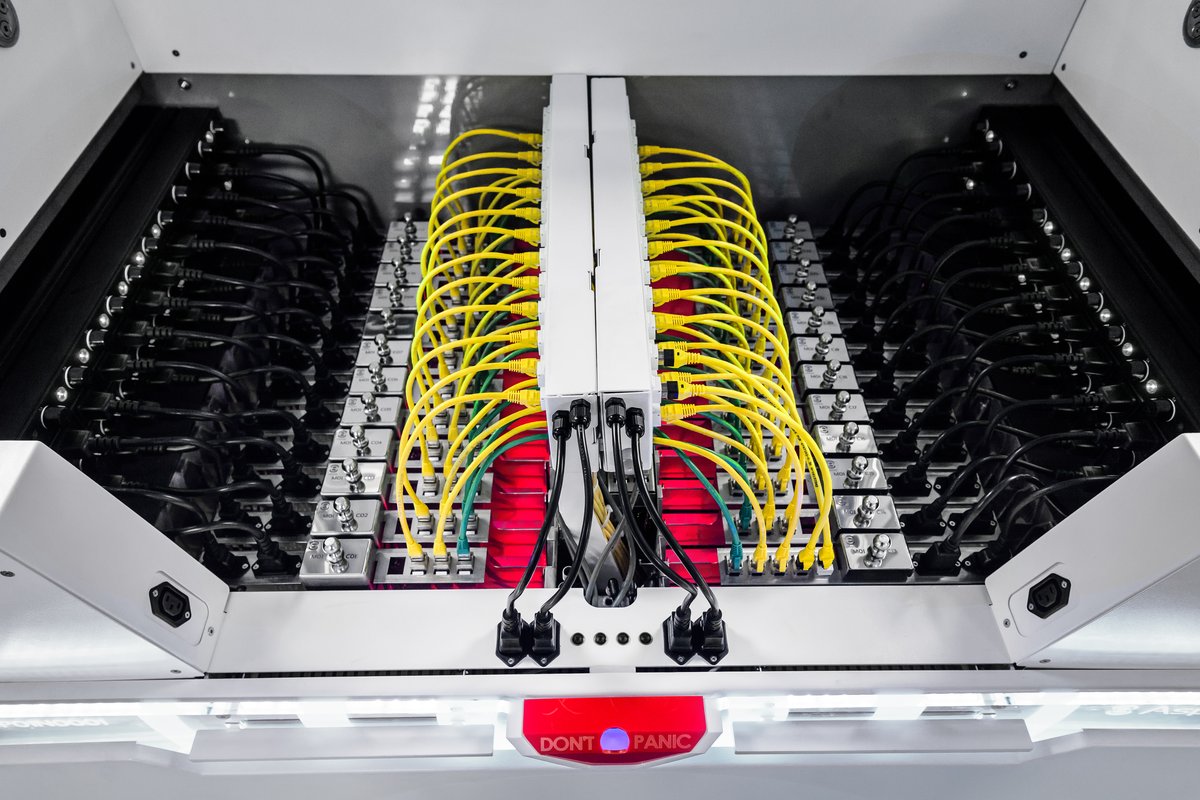
AI loads concentrate power, network, and heat into a few racks. The challenge stops being just total capacity and comes to include transients, power quality, physical distribution, flow rate, return temperature, CDU redundancy, and maintenance of liquid circuits close to the electronics.
| Topic | Design questions |
|---|---|
| Power | What peak, ramp, and diversity per cluster? |
| Network | What topology, latency, cabling, and space for optics? |
| Liquid | What water class, temperature, pressure, quality, and responsibility? |
| CDU | Redundancy, heat exchange, pumps, control, and bypass? |
| Risk | Detection, containment, dripless connectors, and response? |
| Operation | How to drain, purge, maintain, and expand without stopping? |
Even if the first phase is air cooled, reserve routes, technical area, structural load, hydraulic points, electrical capacity, and instrumentation for high-density pods. Improvised retrofits tend to create dependencies and downtime.
Deployment roadmap
| Phase | Verifiable outputs |
|---|---|
| 0. Strategy | BIA, build/buy options, site shortlist, and business case |
| 1. Preliminary study | Load, area, risks, concept, schedule, and budget |
| 2. Conceptual design | Architectures, diagrams, criteria, and estimate |
| 3. Basic and executive design | Calculations, details, specifications, BoQ, and test plans |
| 4. Contracting | RFP, equalization, responsibilities, and milestones |
| 5. Construction | QA/QC, safety, changes, and evidence |
| 6. Commissioning | Tests by level, IST, training, and punch list |
| 7. Operation | Handover, baseline, SLA, maintenance, and improvement |
Each phase must end with approval criteria. The gate does not exist to add bureaucracy, but to prevent critical uncertainties from advancing and turning into expensive changes. Unmet requirements must be corrected, formally accepted as risk, or removed from scope with the impact recorded.
Checklist for RFP and contracting
| Block | Items |
|---|---|
| Scope | Boundaries, interfaces, inclusions, exclusions, and responsibilities |
| Performance | Capacity, autonomy, efficiency, availability, and environment |
| Design | Standards, deliverables, review, BIM/CAD, and change control |
| Supply | Accepted brands, equivalence, FAT, logistics, warranty, and parts |
| Construction | Plan, safety, QA/QC, ITP, schedule, and active environment |
| Testing | SAT, functional tests, load bank, IST, and acceptance criteria |
| Operation | Training, O&M, as-built, support, and SLA |
- Compare technical exceptions, not just total price.
- Normalize efficiency, usable capacity, redundancy, and autonomy.
- Evaluate lead time, obsolescence, and local support.
- Require an item-by-item compliance matrix.
- Tie payment to milestones and performance evidence.
Operational readiness checklist
| Question | Expected evidence |
|---|---|
| Does the team know the sequence of operation? | Recorded training and simulation |
| Do procedures reflect the as-built? | Reviewed and version-controlled SOP, MOP, and EOP |
| Do alarms have a defined response? | Alarm matrix and playbooks |
| Are critical parts available? | Inventory, preservation, and replenishment |
| Have configuration backups been tested? | Proven restoration |
| Do contracts cover the 24x7 scenario? | SLA, contacts, and escalation |
| Is there a baseline before occupancy? | Power, thermal, network, and environment recorded |
Result: the data center is ready when people, processes, documentation, tools, and suppliers can operate and recover the infrastructure — not merely when construction ends.
Quick formulas and conversions
| Topic | Reference relation |
|---|---|
| Three-phase power | P ≈ √3 × V × I × PF × efficiency |
| Energy | kWh = kW × hours |
| Thermal load | 1 kW ≈ 3,412 BTU/h |
| Ton of refrigeration | 1 TR ≈ 3.517 kW thermal |
| PUE | total data center energy ÷ IT energy |
| Simple availability | MTBF ÷ (MTBF + MTTR) |
| Compound growth | future capacity = current × (1 + rate)^years |
The relations above are simplifications for estimation. Executive design requires curves, correction factors, environmental conditions, losses, harmonics, coincidence, and normative criteria.
Conceptual sizing example: IT load of 600 kW, growth to 900 kW in five years, and modular expansion of 150 kW. The strategy can deploy 4 active modules + 1 redundant in the initial phase, reserving space and primary infrastructure for future modules. The analysis must verify whether the system maintains N during maintenance and failure, and whether the auxiliary loads keep pace with each stage.
Recommended technical references
Always consult the current edition, the contracted scope, and local legal requirements. The references below guide the study but do not replace acquisition, full reading, and application by qualified professionals.
| Reference | Application |
|---|---|
| ISO/IEC 22237 | Data centre facilities and infrastructures — concepts, building, power, environment, telecom, security, and operation |
| ISO/IEC 30134 | Key performance indicators for data centers, including PUE |
| ASHRAE TC 9.9 | Thermal Guidelines for Data Processing Environments |
| Uptime Institute Tier Standard | Topology criteria and certification programs |
| ANSI/TIA-942 | Telecommunications infrastructure for data centers |
| NFPA 70 / 75 / 76 / 855 | Electrical, IT and telecom equipment protection, and energy storage systems, as applicable |
| ABNT NBR 5410 / 14039 / 5419 | LV and MV electrical installations and lightning protection |
| ABNT NBR 14565 | Structured cabling for commercial buildings and data centers |
| ABNT NBR 17240 and applicable fire standards | Detection and alarm, plus local Fire Department requirements |
Brazilian legislation, ABNT standards, Fire Department instructions, and environmental requirements must be confirmed for the location and date of the project.
Conclusion
Designing a data center means managing consequences. The best solution is not the one that accumulates the most redundant equipment, but the one that connects criticality, risk, architecture, execution, testing, and operation in a coherent and demonstrable way.
- Hold a requirements and BIA workshop.
- Consolidate inventory, capacity, and expansion horizon.
- Perform due diligence on the site and utilities.
- Produce a conceptual design with alternatives and TCO.
- Define commissioning criteria before contracting.
- Plan handover and operation from the start.
EnQ Digital: intelligent infrastructure for companies that cannot stop — strategy, engineering, deployment, operation, and evolution oriented toward risk and performance.